Many machines on which vibration switches are installed
experience certain non-destructive high-level vibrations during their
normal starting and running conditions. Robertshaw has developed a
"supervisory" (monitoring) system for use with Model 365 and 366 electric
Vibraswitch units. This supervisory instrument is called a MONITOR and/or
CONTROL UNIT. The Vibraswitch instruments used with this monitor or
control unit must have electrical reset coils.
To better understand the reasons for starting and
monitoring time delays, reference to Figure 6 shows typical vibration
levels on an operating machine with respect to time. Since some of these
vibration levels are higher than the set-point adjustment on the
Vibraswitch, the monitor control unit must contain certain supervisory
logic that will sort out the false short term disturbances so that alarm
and shut-down will not occur; but if a valid (long term) high level
vibration occurs, then alarm and shut-down must be initiated
Refer to Figure 6, periods (1) through (5).

(1) STARTING TIME DELAY — The vibration level did
exceed the Vibraswitch set-point. However, the control unit "locked out"
the Vibraswitch control contacts during the time delay periods as set on
the control unit. Without the starting time delay, the machine would not
have reached its normal operating speed because the Vibraswitch would
have shut it down prematurely.
(2) NORMAL VIBRATION LEVEL — After the machine
reaches its normal operating speed and the vibration level has assumed a
level below the set-point value, the Vibraswitch and the control unit are
passive. With the average machine in good mechanical condition. the
"normal" vibration level will dominate for an indefinite period.
(3) TRANSIENT SHOCKS - Monitoring time delay is used to
"sort our" these short duration high level vibrations which are non
destruction to the machine but would cause shut-down. These short duration
disturbances are caused by such things as sudden load changes on pipeline
pumps, by sudden closing of diverting valves, check valves or by air
pockets in liquid lines, pump cavitation, etc. Each time the set-point had
been exceeded by the transient disturbance the monitoring time delay
circuit is energized and the Vibraswitch is reset and a second "sample" is
made to determine if the Vibraswitch requires resetting again. The total
monitoring time is adjustable; usually from 2 to 5 seconds are the most
popular time settings. If the Vibraswitch set-point is not exceeded, then
the control unit remains passive.
(4) DESTRUCTIVE VIBRATION — The sampling and
monitoring circuit is energized immediately on high level vibration
(above the set-point on the Vibraswitch) and approximately five "samples"
will be made during the monitor time period. If all five samples indicate
the vibration level was above the set-point. then the monitor circuitry
will actuate the alarm or shutdown contacts.
(5) ALARM OR SHUTDOWN — The control unit contacts are
locked into the alarm or shutdown conditions until the operator resets the
system.
MODEL 375A AND 376
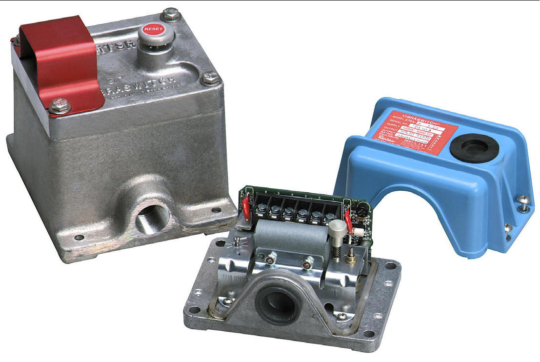
 The Model 375A and 376A
vibration detectors are identical in
outside dimensions and appearance to the famous Model 365 and 366.
However, these instruments include built-in solid state electronic
circuitry for start and/or monitoring time delay functions for prevention
of false shutdowns due to transient vibrations.
The 375A is FM approved for Class I, Division 1, Groups
C & D; Class II, Division 1, Groups E, F & G; and Class III, Div. 1
hazardous locations.
The Electronic Vibraswitch offers complete vibration
protection in a single compact package. It is available at low initial
cost and saves both time and labor in its installation. The instrument is
available in Start Only Time Delay, Monitor Only Time Delay or with both
Start and Monitor Time Delay. For the Start Delay Only version the output
switching is SPDT rated 5 amps at 120 or 240 VAC. The output switching for
the Monitor Only and Start and Monitor versions is a solid state optically
isolated TRIAC which will supply up to 2 amperes at 120 VAC 50/60 Hz. to
an external load.
HOW THE UNIT FUNCTIONS
Start Delay Only models hold the Vibraswitch armature in
its reset position for a preset starting time after application of supply
voltage to the instrument. This prevents the Vibraswitch from tripping out
during machine startup. Fixed timing periods of 15, 30, 60 or 90 seconds
are available. After the time period, the Vibraswitch functions as normal
with shutdown or alarm functions provided by utilizing the SPOT switch
contacts in the Vibraswitch.
Monitor Delay Only models prevent nuisance shutdowns due
to tripping out of the Vibraswitch during high level short term transient
vibration conditions by automatically resetting the Vibraswitch. Under
continuing high vibration, the Vibraswitch trips, is immediately reset,
trips out again, it resets again, etc. This "sampling" process continues
until the time delay period has elapsed, after which the unit remains
"tripped" out. An AC output by means of an optically isolated solid state
TRIAC switch can be used for either alarm or shutdown. The solid state
switching mode can be changed by means of a solderable link to the
equivalent of an NO (for alarm) or NC (for shutdown) electrical contact.
Figure
7
Block Diagram: Start and Monitor Electronic Vibraswitch

Refer to Figure 7 showing the
basic block diagram of the Electronic Vibraswitch for the functional
operation of the unit. For dimensional data, refer to page 6 on Models
365/366.
INSTALLATION AND APPLICATIONS
The Vibraswitch must be mounted on a flat surface so
that all four corners are in rigid contact with the mounting surface. If
the machine has irregular surfaces, a heavy steel mounting plate can be
used, but it must be rigidly attached to the machine. Typically, one-half
inch steel plate is satisfactory and it should be made as small as is
consistent with the size of the Vibraswitch base to reduce resonance
effects. The vibration sensitive axis of the Vibraswitch is perpendicular
to its base; therefore it must be mounted in the correct plane to detect
the vibratory motion for which protection is desired.
A preferable location is in line with rotating main
shafts and as near bearings as is possible. Typical machines requiring
protection are pumps (both reciprocating and centrifugal), fans, blowers,
compressors, gear boxes, mills, turbines, etc.
Model 563A

The Model 563A is a microprocessor based monitor and
control unit. The solid-state electronic system will "sort out" false
signals received by the Vibraswitch so that alarm and/or shutdown will not
result from false transient disturbances. It has field adjustable Start
Delay from 0 to 999 seconds and Monitor Delay of 0 to 99 seconds.
Eight LED indicators, viewable through the window on the
instrument door, are provided for visual indication to determine which
Vibraswitch detected the excessive vibration and triggered the alarm
and/or shutdown.
Optional enclosures are weather-proof NEMA 4 or
explosion-proof for Class I. Division 1, Groups C & D hazardous locations.
The unit is designed for use with one to eight Vibraswitch Models 365 or
366. Power supply options are 120 VAC, 50/60 Hz.; 240 VAC, 50/60 Hz.; 24
VDC or 48 VDC.
MODEL 566

The Robertshaw Model 566 Vibration Monitor is a solid
state instrument that encompasses a variety of functions all in one unit.
Vibration can be monitored in either velocity or acceleration. The
standard ranges are 0 to 1.5 inches/second or 0 to 3 inches/second when
sensing velocity and 0 to 5 G's or 0 to 10 G's when sensing acceleration.
A 4-20 maDC output is standard.
The Model 566 includes two solid state Triacs (2 amp @
120/240 VAC) which can be operated in a N.O. or N.C. configuration. Alarms
are capable of being latched or non-latched (ON-OFF). A time delay
function is also a standard feature and is adjustable from 0.5 to 15
seconds. LED setpoint indicators are provided to indicate the alarm
condition. Options include P/S (120 or 240 VAC) and remote sensor. The
remote sensor can be located up to 1,000 feet away using only a standard
ungrounded pair of twisted wire.
The Model 566 enclosure is designed to be weatherproof
and explosion-proof. The enclosure rating is NEMA 4 and Class I, Division
1, Group C and D; Class II, Division 1, Group E, F and G. Housing for the
remote mounted transducer has the same rating plus Class I, Group B.
Note that on the remote sensor unit the connection from
the Model 566 to the remote sensor need only be two ungrounded wires.
PRINCIPLE OF OPERATION
The Model 566 employs totally solid state circuitry.
Velocity or acceleration sensing mode of operation is field selectable
without loss of accuracy. The unit is factory calibrated in all ranges.
Two alarm setpoints are standard plus use of a built-in 4-20 maDC output.
A machine power monitor input, such as 120 or 240 VAC is
provided to enable the monitor delay and analog output circuitry when the
monitored unit is turned on. The time delay period can be set in the field
up to 15 seconds.
The indicators (LED) will illuminate when the setpoints
are reached. They are electrically connected in the circuit prior to the
time delay to allow for field calibration of the alarm setpoints without
shutting down the machine being monitored.

Alarm # 1 - Operates with adjustable time delay (0.5-15
Sec.). When the vibration signal continues to exceed the setpoint for as
long as the time delay setting, the alarm actuates.
Alarm #2 - Actuates when vibration signal exceeds
setpoint. No time delay function available.
Latch Disable - Disables alarm latches. When on, alarms
reset automatically when vibration level returns to normal.
MODEL
570B AND MODEL 571A
LOOP POWERED STUD MOUNTED VIBRATION TRANSMITTERS

The model 570B is a 10-30 vdc loop powered vibration
transmitter which provides a 4-20 mADC output proportionate to vibration.
The transmitter is available with a measurement range of either 0-5 g,
0-10 g or 0-20 g peak acceleration, or 0-0.5 IPS, 0-1 IPS or 0-2 IPS peak
velocity; and the frequency range is 2 Hz to 2 KHz. This rugged compact
unit provides continuous monitoring of machine vibration for trending,
alarm and/or shutdown when used with a PLC, computer, DCS, data logger or
current relays. The enclosure is 316L stainless steel, NEMA 4X
(hermetically sealed), and meets IP68.
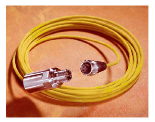
Installation is simple and no calibration is required. A
1/4-28 stud is provided for mounting. The unit has a 2 pin connector and
mates with a standard MIL-C-5015 2 socket connector with a splash proof
connection. Optional cable assemblies are available in lengths of 16, 32,
64 and 112 feet.

The model 571A is a 14-30 vdc intrinsically safe version of
the model 570B. It is CSA Certified for use in the USA and Canada for
Class I, Division 1, Groups A, B, C & D; T3C; when connected to an
approved barrier. For non-incendive environments a safety barrier is not
required. It is also ATEX Certified EEx is IIC T3 for use in Europe when
connected to an approved barrier.

Features and Benefits:
Two wire loop powered (10 – 30 VDC)
4 – 20 mADC output (isolated)
Compact design, 1.12” diameter, 2.80” height
Corrosion resistant (316L Stainless Steel)
NEMA 4X, IP68, hermetically sealed enclosure
ESD and EMI protection
Overload protection
Reverse wiring protection
Available for either acceleration or velocity measurement
CE Certified
No Trim Pots required
