 WARNING: Cancer and Reproductive Harm - www.P65Warnings.ca.gov
TYPICAL VIBRATION SWITCH INSTALLATIONS
TYPICAL INSTALLATION ON A MACHINE
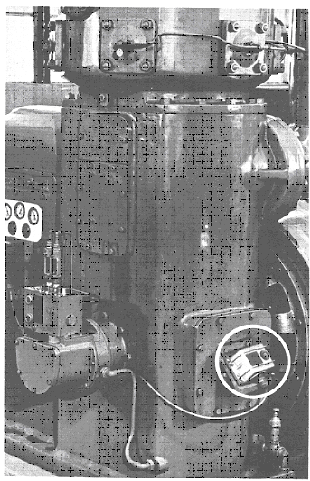 The
photograph illustrates an installation of a Robertshaw vibration switch on a
reciprocating compressor. The sensing unit (detector) is placed on the
machine in a location that will permit the unit to be responsive to
excessive and damaging vibration. In this application the detector is
mounted on a heavy bracket which in turn is rigidly bolted to a heavy
inspection cover located opposite the main crank shaft and bearings of the
compressor. In this location the vibration switch will detect any excessive
vibration due to bearing wear or loose parts associated with either of the
two compressor pistons and their connecting rods which are driven by the
main crank shaft.
The
photograph illustrates an installation of a Robertshaw vibration switch on a
reciprocating compressor. The sensing unit (detector) is placed on the
machine in a location that will permit the unit to be responsive to
excessive and damaging vibration. In this application the detector is
mounted on a heavy bracket which in turn is rigidly bolted to a heavy
inspection cover located opposite the main crank shaft and bearings of the
compressor. In this location the vibration switch will detect any excessive
vibration due to bearing wear or loose parts associated with either of the
two compressor pistons and their connecting rods which are driven by the
main crank shaft.
Typically, the detecting element is placed as close to the bearing
assemblies, crank shafts, driven gears and other rotating or reciprocating
parts as possible in order to be responsive the malfunctions of these
parts
Nearly all rotating or reciprocation machines are
candidates for vibration measuring and control or alarm instrumentation.
The following list of machines are typical: Fans, Blowers, Centrifuges, Turbines, Engines, Mills, Grinders, Alternators, Compressors, Motors, Generators, Gear-Boxes
The types of failures these machines typically suffer most often are: Bearings, Connecting Rods, Pump Impellers, Drive Shaft Couplings, Lubricating systems, valves and valve lifters, Pistons and Rings, Turbine Blades, Belts and Chains, Gear teeth, Seals, Motor Windings, Cavitating Pumps, Dirt Laden Fans, Fractured Belts, Motor Amatures, Part Shifing.
TYPICAL VIBRATION SWITCH INSTALLATIONS
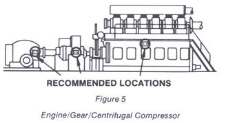 The line drawing shown in Figure 5 indicates typical mounting locations for the
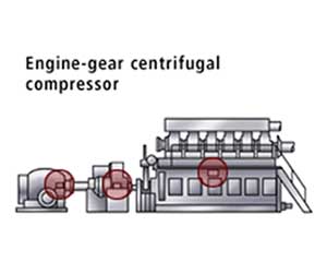
vibration switch detectors on a multiple unit machine (1) consisting of a diesel engine driving into a gear box which in turn is driving a (2) centrifugal compressor. A vibration switch detector is mounted on each of the major units as near the main drive bearings as possible on both the centrifugal compressor and the gear box. The (3) diesel engine is protected by only a single vibration switch located at a mid-point on the engine frame; better protection would be afforded with additional detectors mounted on the engine at the ends of the engine near the drive bearings.
The line drawing shown in Figure 5 indicates typical mounting locations for the
vibration switch detectors on a multiple unit machine (1) consisting of a diesel engine driving into a gear box which in turn is driving a (2) centrifugal compressor. A vibration switch detector is mounted on each of the major units as near the main drive bearings as possible on both the centrifugal compressor and the gear box. The (3) diesel engine is protected by only a single vibration switch located at a mid-point on the engine frame; better protection would be afforded with additional detectors mounted on the engine at the ends of the engine near the drive bearings.
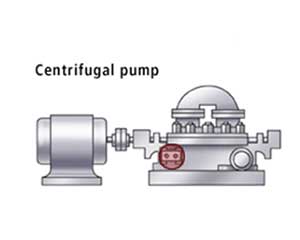
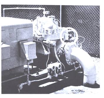 Typical installation of an explosion-proof vibration switch on a motor driven centrifugal
pumping unit. The circled area indicates the mounting location of the vibration
switch on the centrifugal pump used in a petrochemical pipeline
installation at one of the pumping stations.
Typical installation of an explosion-proof vibration switch on a motor driven centrifugal
pumping unit. The circled area indicates the mounting location of the vibration
switch on the centrifugal pump used in a petrochemical pipeline
installation at one of the pumping stations.
The drive motor is a 600 hp, 3500 rpm unit driving directly a high
pressure centrifugal pump operating at approximately 450 psig.
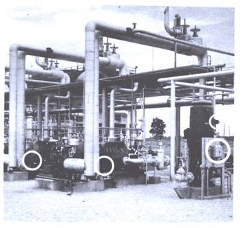 Multiple vibration switch installations at a liquified petroleum gas production facility. The unit circled at the extreme right of the photograph
shows an explosion proof vibration switch and associated control unit mounted on the motor drive unit of a vertically driven pump. The vibration
switch is mounted approximately at the motor mid-point so that it will be responsive to any excessive vibration of either the motor or the vertical pump. The motor drive speed is 4500 rpm. The control unit is mounted on a free standing vertical panel along with Start, Stop and Reset switches required by the system.
Multiple vibration switch installations at a liquified petroleum gas production facility. The unit circled at the extreme right of the photograph
shows an explosion proof vibration switch and associated control unit mounted on the motor drive unit of a vertically driven pump. The vibration
switch is mounted approximately at the motor mid-point so that it will be responsive to any excessive vibration of either the motor or the vertical pump. The motor drive speed is 4500 rpm. The control unit is mounted on a free standing vertical panel along with Start, Stop and Reset switches required by the system.
The circled areas to the center and left of the photograph shows the installation of additional vibration switch detectors on motor driven centrifugal pumps at this LPG processing facility.
RECOMMENDED INSTALLATION LOCATIONS
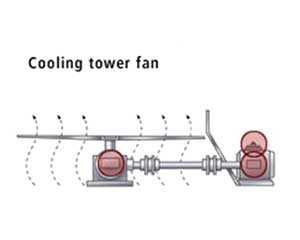
Cooling Tower Fan
Engine Gear Compressor
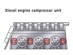
Diesel Engine Compressor
Centrifugal Pump
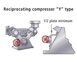
Compressor
Additional Information
Understanding the Physical Characteristics of Vibration
Typical Vibration Switch Installations